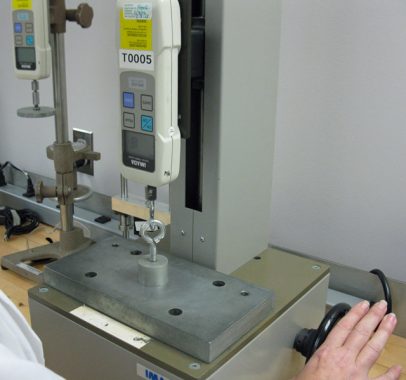
![]() Breakaway force, holding force, fixturing force – “How can all of these represent the same measurement?” a younger engineer recently inquired. Engineers and non-engineers alike can be puzzled trying to understand some of the commonly used – but potentially misinterpreted – terms related to the concept of a magnet’s pull force.
Breakaway force, holding force, fixturing force – “How can all of these represent the same measurement?” a younger engineer recently inquired. Engineers and non-engineers alike can be puzzled trying to understand some of the commonly used – but potentially misinterpreted – terms related to the concept of a magnet’s pull force.
These phrases are often used to represent “strength” when writing magnetic specifications. They also may be mentioned when anticipating the work required of a magnet within an application. To add to the potential confusion, the maximum holding force, or how much tensile force is exerted by any magnet, is often shown in online calculators – like our neodymium pull force calculator – are based on theoretical calculations of flux density.
One assumption, which may or may not be accurate, is that there is no air gap, or separation between magnet and work piece. Another important “real world” factor that differentiates breakaway force from a required safety consideration is the environment in which the magnet will be used.
Derating, or a reduction in the stated (breakaway) force value of a magnet, may be required depending upon the industry to help avoid safety hazards associated with their use. A “below the hook” application would derate (or reduce the stated force) by a factor of three. Derating (also sometimes written as de-rating) provides an established way to over-engineer reducing safety hazards. An example to help illustrate an application associated with under the hook magnets is a steel plate lifting station on a manufacturing plant floor.
People, plant, equipment, and services in the area of operation could be at risk from being struck by material which becomes detached from the magnet if it was lifting AT THE TRUE STATED MAXIMUM with this derating value being applied.
There is no simple way to calculate the breakaway force if the magnet is not in direct contact. Virtual prototyping of magnets allows us to help customers save time and money. This is where a $30,000 modeling software comes into play.
Within the Public Domain, there are several programs available for measurement and modeling of Finite Element Method Magnetics (FEMM). One such software package – MagNet 2D/3D – is a powerful simulation software which engineers and scientists worldwide use for the design of motors, sensors, transformers, actuators, solenoids, or any component with permanent magnets or coils. Using this software allows engineers to virtually prototype simple to complex electromagnetic and electromechanical devices.
As mentioned earlier, engineers may not have taken into account air gap. If the magnet is not going to touch the workpiece due to, for instance, scale built up on steel plates, or a physical distance between workpiece and magnet, the air gap becomes very important in calculating the ACTUAL requirements of the magnet under its specific working conditions.
Often, a holding magnetic application comes into our application engineers in which a defined pull-force has been specified. The true engineering phase is identifying the required (and optimally priced) magnet to use to achieve the desired attractive force.
Typically, in many applications, there will be a set of constraints: “only so much room for the magnet,” etc. These size dimensions, along with the actual proximity of workpiece to magnet in turn must be factored in to calculate the breakaway value. This can necessitate investigating alternate grades of magnet to complete the specification. For example, using a bigger magnet that is grade 35, or using a smaller magnet that is grade 45.
Magnetic pull force measurement and specification can be complicated
Dura Magnetics is available to assist with designing magnets for your applications. Our engineers, using powerful simulation software, work directly with engineers worldwide to specify precision custom magnets. Contact us today to get started on the solution for your next project.


